  |
|
The Nixie Tube Propeller Clock has spun
times since midnight!
|
|
|||||||
| Nori Clock Firmware | |||||||
|
OverviewThe firmware for the Nori Clock manages the clock's entire operation, including timekeeping, button handling and display updates. Like for the Phone Call Monitor, the firmware was written in C and built with the MPLAB C18 compiler suite. This time I used Microsoft's Visual Studio Code as the code editor, but not wishing to deal with the intricacies of the MPLAB X IDE or the Microchip toolchain's integration with VS Code for this single project, I decided to stick with the good old MPLAB v8.92 for building, flashing and debugging the firmware. The source code can be found at the NoriClock GitHub repository. PIC/C18 CaveatsBecause of the unique architecture and limited resources of PIC microcontrollers, there are multiple special features of the MPLAB C18 compiler to keep in mind. ROM vs. RAM DataIn the PIC18's Harvard architecture, the program memory (ROM) and data memory (RAM) are separate address spaces. This means that pointers to ROM and RAM cannot be used interchangeably; the C18 compiler provides the rom qualifier to indicate that a pointer points to ROM. This is of particular importance when dealing with strings. To save precious RAM space, it is practical to place constant data to program memory; in case of string literals, the compiler automatically puts them there. As it is explained in the Driving the Display section of the PCMF firmware page, the special putsVFD() API had to be implemented to send data to the display. In order to conveniently use this function for constant strings as well, they need to be scooped over to the RAM-based msg_buff buffer first. The case is even trickier for the sprintf() library function; it prints into RAM, and while it expects the format string from ROM, the arguments for the "%s" format specifier must reside in RAM. (This threw me a bit off-kilter initially, until I figured out why certain printouts were not working.) Integer PromotionsThe ISO standard mandates that all arithmetic be performed at int precision or greater. This is referred to as integer promotion, and the compiler adds a significant overhead (about 5% for the Nori Clock FW) to support it throughout the code. However, this is often an overkill for projects using a PIC MCU, therefore it can be opted out of in the C18 project settings. After doing so, I carefully audited all the expressions that were affected by this change and applied explicit up-casts accordingly. (It is important to note that even in expressions, where both the arguments and the result are of the byte type, a sub-result may escape that boundary, as is the case with the calculation of dow_jan1.) Firmware ArchitectureThe firmware consists of the event-driven "background" Main Loop and a single ISR triggered by the Timer 0 overflow interrupt. The ISR is responsible for keeping the time and maintaining the USER button state machine, while the display update takes place in the Main Loop due to its relatively slow execution. (The SPI communication itself is fast, but the VFD has a sophisticated command set and virtual window support, therefore rendering the display is a time-consuming task.) Timer ConfigurationThe Nori Clock firmware utilizes the MCU's Timer 0 and Timer 1 modules, as explained below. Timer 0, the Time-KeeperTimer 0 is the heart of the "clock movement". As it is explained on the Hardware page, the Nori Clock uses a 16 MHz TCXO as the MCU's clock source. This results in a 4 MHz instruction cycle frequency, from which Timer 0 is clocked with no prescaler. It is used in 16-bit mode, with the overflow interrupt enabled. Because this time the MCU clock frequency does not factor into a high-enough power of 2, it would not have been practical to operate Timer 0 in free-running mode. Rather, it is reloaded in the ISR, with the upside that now I had the flexibility to choose any arbitrary IRQ tick frequency. I settled with 100 Hz (10 ms), which is ideal for debouncing the USER button, while keeping it responsive enough even for the quickest fingers. Ideally, the reload value in this case would be 25536 (as in 65536 ‑ 40000), but more on that later [↓]. Timer 1, the Delay StopwatchThe VFD's boot sequence requires some delays in the μs...ms range, which could have been implemented with the delay functions offered by the MPLAB C18 libraries that cover different time spans with different resolutions. However, that approach felt rather clumsy to me; so I cooked up my own solution instead, using Timer 1 in 16-bit mode, clocked through 1:4 prescaling at 1 MHz. The resulting single delay_us() function can delay up to 65.5 ms, with microsecond-resolution. DEBUG Signal UsageIn the final design, the DEBUG signal conveys information with the following encoding:
Shoehorning these two functionalities into a solo signal made it possible to use the only available debug header pin, and nothing more. In addition to convenience, the two occurrences are also easier to correlate this way. For example, the final ISR pulse before the end of an idle period marks the passing of a second or a button event; the duration of this pulse shows the ISR execution times in the different scenarios.
The first scope shot shows the DEBUG signal over the course of a couple of seconds, while the second shot zooms in on a non-idle period. As can be seen from the traces, the display printout takes 140 ms, while the ISR execution times are very short (a mere 18 μs between seconds; 120 μs for a typical second, but can go up to 670 μs when day-of-week and DST status recalculation is needed). Display MattersJust as in the PCMF, the communication with the VFD is done in SPI Mode 11, but the SCLK frequency got bumped up to 1 MHz. I also made some improvements to the code, such as:
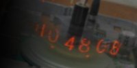
Since the display looks much better when it is not inverted, the clock is intended to run in non-inverted mode at all times; it is highly unlikely that this gadget (or the VFD itself) would be used for anything else in the future, so the potential burn-in of pixels is not a grave concern anymore. However, out of curiosity I did test the brightness of all pixels after two months of operation, and made a startling discovery: the always-off pixels ended up slightly dimmer than the ones that get illuminated on the regular clock display. ("If you don't use it, you lose it", as the old adage goes.) The photo below demonstrates the artifact.
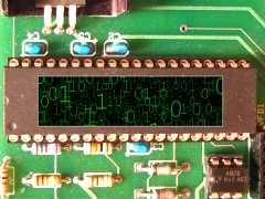
For this reason, I added the inverted display modes that should be dialed in from time to time, to shake up the neglected pixels. Another display mode turns on all pixels, to check on their current health. It turned out, however, that this is also related to the age of the display. The one in the picture had been in service for almost two decades; after I swapped it out with the second display in my possession, which has never been used before, the issue is not present even after a month of use. (Regardless, running the display in inverted mode from time to time is probably a good idea.)
I did not have any more green acrylic sheet for this display, to make that nice warm green glow. However, the upside is that the clock can now operate with the low brightness setting, and still be fully readable by daylight. In Search of Lost TimeBack to the Timer 0 reload value for a second... Since vectoring the ISR and the context save beforehand do consume some instruction cycles, it was expected that the reload value would be smaller than the calculated ideal one. For this reason, I ran a DOE (the self-aggrandizing lingo for "experiment") to determine what the correction should be. What I found, however, became another head-scratcher, as the result came out to be a whopping 380. My first thought was that I got a spoiled TCXO, but a frequency measurement quickly debunked that theory. Finally, a quick look at the assembly of the compiled code revealed the culprit: the ISR prologue generated by the compiler saves the compiler-managed resources, which I was aware of, but was more extensive than I thought. While the originally discovered correction value would have worked perfectly fine, I wanted a solution that did not depend on any future compiler changes. To achieve this, I inserted a small assembly snippet between the interrupt vector and the ISR's C function, which reloads the timer before the ISR prologue kicks in. (Since on this MCU the W register - among some others - is automatically saved as soon as the ISR is invoked, I did not have to worry about saving it explicitly.) In the next DOE, I clocked the clock from a signal generator with precise 16 MHz; this revealed that there are only 10 instruction cycles between the Timer 0 overflow and the completion of its reload. DST PoliciesWhoever came up with the idea of Daylight Saving Time first (accounts vary) had no idea about the calamity it would cause in the computer age. This reckless warping of spacetime is responsible for the countless file timestamp headaches, out-of-sync subsystems, etc. (I have even encountered IoT devices that refused to do firmware upgrade on the days of DST changeover.)
The Nori Clock carries out the DST adjustments automatically, with the US observance days hardcoded into the firmware. (Let us hope they will not change again anytime soon...) The question still remains as to what should be done when the time is set. Obviously, whatever the user dialed in should be taken at "face value" (i.e., with no time adjustment of any sort, even if the clock was not frozen at the time of setting and DST changeover just happened during that time), updating the new DST status accordingly upon exit from setting mode. However, there are some gray areas on the changeover days, which the firmware handles the "natural" way, without any special-casing. Using the bottom of the hour as an example, the following scenarios can occur:
There is also an increasing push to abolish DST altogether, or to make it permanent (called War Time, as it was applied during the two World Wars). Fortunately the Nori Clock is ready for such a change, as DST can be disabled. |
||||||

")


|