  |
|
The Nixie Tube Propeller Clock has spun
times since midnight!
|
|
||||||||||||||||||||||||||||||||||||||||||||||||||||||||||||||||||||||||||||||
| Sound Engine Deep Dive | ||||||||||||||||||||||||||||||||||||||||||||||||||||||||||||||||||||||||||||||
|
MotivationHaving realized that the firmware is spending 99.7% of its time in the PtDelay subroutine doing essentially nothing, I decided to gift the clock with the ability to play music. On the hardware-side, a small piezo buzzer was dropped into the circuit board and hooked up to a still available GPIO. (Not quite an audiophile choice, but then again, the Nixie Tube Propeller Clock is not a Moog synthesizer...) This video demonstrates all the different music options, including the two test sounds. Theory of OperationThe basic idea is that the Point Loop, which originally served the sole purpose of administering the necessary delays for the POV display, got interwoven by a secondary loop, generating tones bare-metal pulse-banging style. One advantage of programming a PIC MCU in assembly is that the firmware has very close control on the execution of the PIC's simple instructions, which made this challenge possible with high accuracy. Architecting the SolutionThe sound engine makes the sound by toggling the buzzer's GPIO with 50% duty cycle; the length of the on/off-periods is adjusted according to the desired frequency. Within the spinning loop of PtDelay, this can be achieved by decrementing a register from a given value, referred to as the pitch divider, until it reaches zero. The goal was to cover a little more than two octaves, and my calculations showed that it could be achieved with reasonable accuracy using a pitch divider of 8-bit resolution, which is good news, the PIC being an 8-bit MCU. However, this would have yielded a minimum frequency of around 3.2 kHz - not the most pleasant experience for the human ear. Enter the pitch divider multiplier, which divides the frequency by effectively multiplying the pitch divider by an integer value. (In retrospect, it is a bit awkward terminology, but now it stuck.) The code snippet below shows the resulting implementation of the Core Loop, responsible for churning out the pulses. (The code takes massive advantage of the macros I defined for the PIC MCU, to make its rather cryptic assembly easier to follow.)
For the derivations that follow, the table below lists the cast of characters, with their symbols in the formulas, their identifiers in the code and their values (whichever applies). In the symbols, subscripts indicate a "per" relationship, for example "ci" means "[instruction] cycles per [Point Loop] iteration".
Tuning the Pitch Divider MultiplierThe number of instruction cycles between two consecutive toggles of the buzzer GPIO, i.e., a half-period of the sound signal, can be calculated with the following formula: $$\begin{align*} c_{hp} &= 6 \cdot (D - 1) \cdot d + 10 \cdot (d - 1) + 13 \\ &= 3 + (4 + 6 \cdot D) \cdot d \end{align*}$$The three terms above reflect the number of instructions executed in the Core Loop with neither countdowns, the pitch divider multiplier countdown or both countdowns reaching 0, respectively. (The Djnz macro, inspired by the "decrement & jump if non-zero" instruction of the once-popular Z80 microprocessor, takes 3 instruction cycles if the decremented register is not zero, but only 2 cycles if zero.) For a full period, $$c_{fp} = 6 + (8 + 12 \cdot D) \cdot d$$Since the MCU is clocked from a 19.6608 MHz crystal oscillator, and one instruction cycle takes 4 clock cycles, the frequency of the emitted sound is $$\begin{align*} f &= {c_s \over c_{fp}} \\ &= {4,915,200 \over {6 + (8 + 12 \cdot D) \cdot d}} \end{align*}$$The necessary pitch divider multiplier is determined by the lowest frequency that the sound engine needs to be able to play; I picked G4, the G note in octave 4, typically referred to as middle G. This is the lowest note in the Woodycock melody, which is already played one octave above, due to the buzzer's characteristics. (As a matter of fact, even these frequencies are a bit too low for the piezo buzzer; rather, it will "pick up" the harmonics from the square wave that are more to its liking. For the regular music options, this just means a higher octave; but in case of the frequency sweep test sound, the Shepard tone phenomenon can be observed at the very high pitches.) The frequency of G4 is 392 Hz, therefore applying the largest pitch divider of 256, we get $$392 = {4,915,200 \over 2054 + 3072 \cdot D}$$ therefore $$\begin{align*} D &= {{4,915,200 \over 392} - 2054 \over 3072} \\ &= 3.41 \end{align*}$$By setting the pitch divider multiplier to 4, there will be some extra slack in the low-end of the scale. With this question settled, $$c_{hp} = 3 + 28 \cdot d \\ c_{fp} = 6 + 56 \cdot d$$ which then yields $$f = {4,915,200 \over {6 + 56 \cdot d}}$$From this, the (unrounded) pitch dividers for the different notes could be calculated as $$d(note) = {{{4,915,200 \over f(note)} - 6} \over 56}$$However, this is just the first approximation, as the correct pitch dividers are slightly different. Correcting for the Point LoopThe ointment in the soup is the Point Loop, the actual reason for the existence of the PtDelay subroutine. The problem is that the above calculations did not factor in what happens upon the passage of 1 point's time period, but this does occur during a single cycle of the sound signal many times (with a frequency of exactly 12000 Hz, to be precise). The code snippet below highlights the Point Loop that surrounds the Core Loop (only presenting the instructions that run in case of a rotating display); whenever a point elapses, 7 extra instruction cycles are executed.
To quantify the effect of the Point Loop on the generated frequencies, we need to determine ip, the number of [Point Loop] iterations per point - and for that, we need to know the number of clock cycles per individual iteration. Without considering the Point Loop, the average number of iterations can be expressed as $$\begin{align*} c_i &= {c_{hp} \over {D \cdot d}} \\ &= 6 + {4 \over D} + {3 \over {D \cdot d}} \end{align*}$$but with the effect of the Point Loop added, we get $$c_i = 6 + {4 \over D} + {3 \over {D \cdot d}} + {7 \over i_p}$$For D = 4, this evaluates to $$c_i = 7 + {0.75 \over d} + {7 \over i_p}$$We also know that there are 1000 points per arc (per definition), 2 arcs per revolution (for the time & date) and 6 revolutions per second (which is the floppy motor angular speed), therefore the number of points per second is $$\begin{align*} p_s &= p_a \cdot a_r \cdot r_s \\ &= 1000 \cdot 2 \cdot 6 \\ &= 12,000 \end{align*}$$The ideal number of instruction cycles required for a point can be calculated from the number of instruction cycles per second as $$\begin{align*} c_p &= {c_s \over p_s} \\ &= {4,915,200 \over 12,000} \\ &= 409.6 \end{align*}$$This is true in theory; however, PtDelay is only in possession of the processor about 99.7% of the time. Outside of that, the MCU is actually doing something useful, i.e., it calculates the digits, renders the display and handles the Timer IRQ. After carefully measuring these "busy" periods, the correct ideal instruction cycles per point came out to be $$c_p = 408.288$$The number of necessary Point Loop iterations is $$\begin{align*} i_p &= {c_p \over c_i} \\ &= {c_s \over {p_s \cdot c_i}} \end{align*}$$so based on the above, we can get ip by solving this system of equations: $$\begin{align*} c_i &= 7 + {0.75 \over d} + {7 \over i_p} \\ i_p &= {408.288 \over c_i} \end{align*}$$There is one problem, however: the formula for ci contains the pitch divider, in other words, the music being played ever-so-slightly changes the timing of the points. It must be pointed out (pardon the pun) that this exercise is 100% academic, as the effect is completely unnoticeable on the rotating display patterns for normal music, and the stationary ones use the photodiode to stabilize the display; the name of the game is merely to keep the quasi-stationary test pattern as steadfast as possible. This is certainly hair-splitting in this particular application, but engineering pride demands the best solution imaginable. To get a rough idea about the required iterations per point across the board, let us plug in the (slightly incorrect) pitch dividers resulting from the original d(note) formula from the previous section. For all normal sounds (i.e., the notes in octaves 5 and 6), the ip results center around the value of 57 and some fraction. However, in order for the point delays to be accurate, they need to be as close to a neighboring integer possible. One trick to bring the fractional value down is to add extra instruction cycles to the Point Loop. Therefore we can settle with 57 as the ideal number of iterations per point, and observe what new set of pitch divider values this Point Loop yields, as a function of the newly inserted instruction cycles. If we assume that the usual music plays the notes between E5 and E6 uniformly (which is a good approximation for the currently implemented music options), let our "golden" pitch divider be from "the middle of the pack", i.e., the reciprocal of the average of pitch divider reciprocals for the aforementioned notes. This comes out to be around 90, so with this target in mind, let us check which values of k and d would bring ip closest to 57.0 - in other words, when will the $$57 = {408.288 \over {7 + {0.75 \over d} + {{7 + k} \over 57}}}$$equation hold. The solutions are tabulated below:
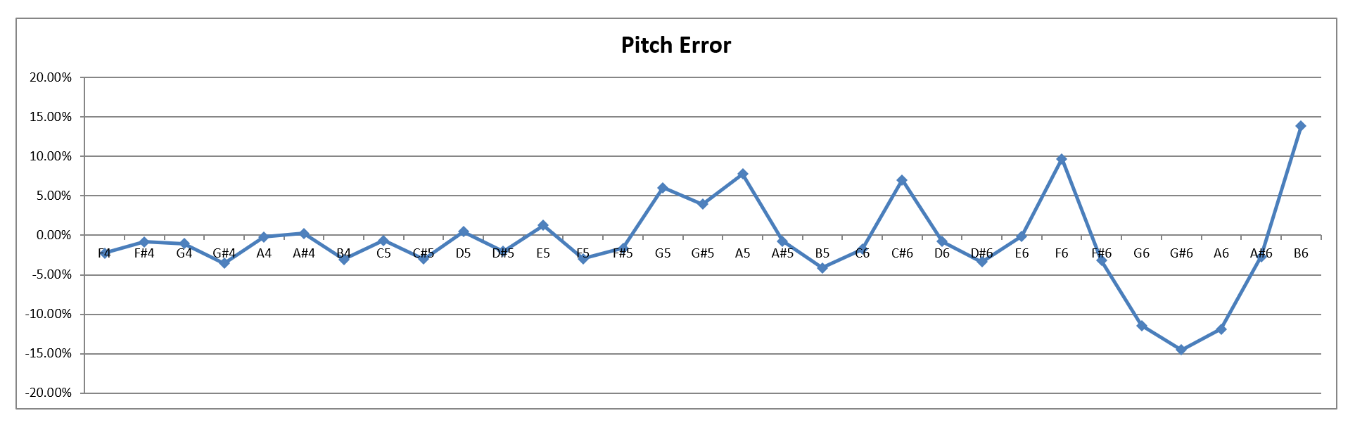
For k = 1 the resulting pitch divider corresponds to a note that is very high up, but for k = 2 the value of 149 is acceptable, making the "average" music pull the quasi-stationary display clockwise just a teeny bit, since the higher note frequencies add a minuscule amount of time to the point delays. (Note that inserting extra instructions in the pitch divider multiplier loop would have too much of an impact, while inserting them into the pitch divider loop would make the timing more sensitive to the played notes.) The updated formula for the instruction cycles per iteration is therefore $$\begin{align*} c_i &= 7 + {0.75 \over d} + {9 \over 57} \\ &= 7.158 + {0.75 \over d} \end{align*}$$This pitch divider of 149, thus far purely theoretical, in fact has a very practical application. Being the one that yields the most ideal ci, it is assigned to what is called the Silent Note. When the sound is off, the sound engine keeps playing the corresponding frequency (around 576 Hz), even though the buzzer itself is disabled. This ensures that in the majority of the clock's life (let's be honest about it...), the display's timing is the most accurate. Recalculating the Pitch Dividers and FrequenciesUsing the updated formula above, the relationship between sound frequency and pitch divider becomes $$\begin{align*} f &= {c_s \over {2 \cdot D \cdot d \cdot c_i}} \\ &= {4,915,200 \over {6 + 57.263 \cdot d}} \end{align*}$$therefore the pitch dividers can be recalculated as $$d(note) = {{{4,915,200 \over f(note)} - 6} \over 57.263}$$Their rounded values form the lookup table that is baked into the firmware. Because of this rounding, however, the produced notes will somewhat diverge from their ideal frequencies in the equal temperament scale. The error is defined as $$error = 12 \cdot log_2{f_{actual} \over f_{ideal}}$$and so +/-100% means that the actual frequency strayed all the way to a neighboring note. The graph below shows the error for the notes supported by the sound engine.
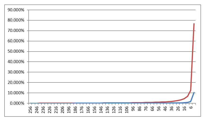
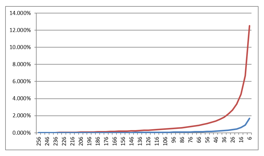
The error starts swinging around a bit at higher frequencies - but for our purposes it is good enough, and who knows, some musician may decide to start using this unique NTPClock scale in the future... Core Loop Implementation CaveatFrom the code itself it is not patently obvious, but the pitch divider multiplier loop is in fact nested inside the pitch divider loop - and this order is important. Below is the current formula for the instruction cycles per Core Loop iteration (for D = 4): $$\begin{align*} c_i &= 6 + {4 \over D} + {3 \over {D \cdot d}} + {9 \over 57} \\ &= 7.158 + {0.75 \over d} \end{align*}$$Now let's imagine that D and d swap places: $$\begin{align*} c_i &= 6 + {4 \over d} + {3 \over {d \cdot D}} + {9 \over 57} \\ &= 6.158 + {4.75 \over d} \end{align*}$$In the second formula, the numerator is more than 6 times larger, and therein lies the problem: for small values of d, that term really blows up. The graphs below show the increase of ci as the function of d, with respect to the starting value at d = 256; the red curve represents the "clumsy" approach. (The second graph excludes the extreme d = 1 case, to make the rest of the curves easier to see.)
Intuitively, the reason is that in the inferior nesting, a bigger part of the code is subjected to the conditional execution that depends on the variable value of d. The math confirms this, and also provides quantitative results. With all that said, even the better solution increases ci significantly for very small (and thus unused) values of d. This is the reason that at the very end of the frequency sweep test sound, the quasi-stationary display (selected for this particular test) suddenly jolts to the right, as shown in the video at the top of the page. ConclusionThe above study explains how it was possible to resolve the tug of war between the two users of the Core Loop to the satisfaction of both. Precise timing is achieved through carefully managing code execution down to the instruction-level.
|
|||||||||||||||||||||||||||||||||||||||||||||||||||||||||||||||||||||||||||||



|

