  |
|
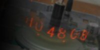
The Nixie Tube Propeller Clock has spun
times since midnight!
|
|
||||||||||
| NTPClock Firmware | ||||||||||
|
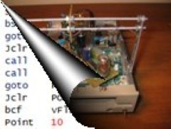
OverviewThe entire firmware of the NTPClock was written in the assembly language of the MCU; while it also saves code space, the main reason for this choice was the need to have control over timing at the instruction cycle level for display and sound generation. Arguably, the PIC assembly is not particularly user-friendly; to remedy this, I added a set of macros that replace or improve the most counter-intuitive instructions. The firmware source code can be found at the NTPClock GitHub repository. Firmware ArchitectureThe NTPClock firmware has two main components:
The background code is a very simple infinite loop with only two subroutine calls; one that converts the binary clock field values to decimal, and the other that generates the display on the spinning Nixie and produces the sound. However, the devil without a doubt is in the details... Timing and Time-KeepingIn the NTPClock, the MCU's clock source is the built-in high-speed oscillator using an external 19.6608 MHz crystal. While this number may not say much at first glance, recognizing that it is in fact 218⋅3⋅52, the reason this crystal exists becomes more clear. Since in the PIC one instruction cycle consists of 4 clock cycles, the free-running 8-bit Timer 0 clocked through the 1:256 prescaler setting will trigger an overflow interrupt at 75.0 Hz, which means that counting out an exact 1‑second time period is simple. Furthermore, the 13.3 ms cycle time is long enough to debounce the Control button, but short enough to discern the different button press patterns. Generating the DisplayThe full display circle is output as two half-circle sections, referred to as arcs - one for the time and one for the date. Each arc is divided into 1000 segments called points. The firmware controls the timing required for the different angular displacements of the Nixie tube in point units via the very carefully crafted PtDelay subroutine, which is wrapped into the Point macro to provide an intuitive interface. Most point-values come directly from the desired display geometry. One exception is the amount of time a digit is lit up on the Nixie (defined by the cDIGLTP constant in the code), which was experimentally tuned to ensure that the digits are bright enough, but not smudged. The different scenarios are explained below. The attached figures demonstrate the two arcs of the display; orange represents the actual printouts, while the gray sections stand for the "padding" of the arcs. The darker gray post-string pause carries special importance, as it determines the speed and direction of a display pattern's scroll. Scrolling Display PatternsWhen the sum of delays in the arc results in the Nixie tube covering other than 180° along its path, the display will rotate. Point delay ΔP is the value, by which the post-string pause needs to be modified to get a certain display scroll; it is calculated as: $$\Delta P = 1000 \cdot {\omega_{scroll} \over \omega_{spin}}$$where ωscroll is the angular velocity of the display scroll, and ωspin is that of the Spinning Board with the Nixie tube (360 rev/min). Note that for clockwise display scroll ωscroll is negative, as the floppy motor is spinning anti-clockwise. A scenario like that is illustrated by the figure below; since ΔP is negative (i.e., the post-string pause is shortened), the two arcs will add up to less than 360° total. The white gap section does not actually occur; rather, a new arc begins as soon as the previous one ends, causing the display to scroll clockwise.
Stationary Display PatternsFor these patterns, ΔP is set to a small positive value, but rather than allowing for an anti-clockwise scroll, the arc is "cut to size" because the post-string pause is terminated as soon as the Index Hole is seen by the photodiode. The figure below visualizes this scenario. The yellow dot marks the position of the Nixie tube at the moment when the Index Hole is seen; this ends the post-string pause, which otherwise would have stretched all the way to the dotted line. (The amount of angle distortion is exaggerated for demonstration purposes; in reality, it is a mere 5 points per arc, which means 1.8° over the entire circle.)
Note that the Index Hole's transit only happens for one of the arcs; the other one will "time out" naturally. The former case also informs the firmware that the upcoming arc will be in the front. Quasi-Stationary DisplayWhen ΔP is set to zero, the display becomes stationary, at least in theory. I first added this as a test mode to tune the different timing constants, then decided to keep it as an interesting feature. Because the clocking of the PIC and the floppy motor electronics are asynchronous, slight variations in the frequencies (e.g., due to changes in temperature) will cause the display to eventually creep away from its original position. With the addition of the sound engine, the aim at perfect synchronization is no longer applicable; this made the Index Hole even the more essential for [true] stationary patterns. MagnetoSpinI discovered this pattern totally by accident during experimentation. In this mode, the display scrolls anti-clockwise quickly, but slows down when the arcs are around the middle position, so that the one in the front can be read out. This is achieved by reducing ΔP from a large to a small positive value during the Index Hole's "transit" over the IR LED. The video below shows all the different display patterns. Generating the SoundsMy measurements determined that the MCU spends approximately 99.7% (!) of its time (all but about 270 µs per each 83.3 ms arc) in the dumb spinning loops of the PtDelay subroutine, which is an egregious waste of computing resources. However, the PIC being too limited for mining crypto or training LLM's (the latter wasn't even a trend at the time), I got the idea to use these idle periods to generate sound via a piezo buzzer, which was attached to a still available GPIO. The sound engine that toggles the buzzer's GPIO purely from firmware was meticulously worked into the inner loop of PtDelay. The calculations that determine how to put the desired frequencies on the GPIO are rather complex, and were done offline; the gory details are described on the Sound Engine Deep Dive page .The smallest unit of note duration the sound engine can play is the time it takes to draw one arc. This is associated with the length of the sixteenth musical note, and the commonly used multiples are also supported, all the way up to the whole note. There is also an option to sound out a note through the entire period vs. "staccato-style" for the Manic Miner and Jet Set Willy jingles. Writing tunes is made easy by the formalism provided by constant definitions and the N(pch,dr) macro, which allow specifying the pitch and duration of a note in an intuitive form. For example, N(G5,V1_2) represents a G5 half note. |
|||||||||


|