  |
|
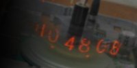
The Nixie Tube Propeller Clock has spun
times since midnight!
|
|
|||||||
| PCMF Hardware | |||||||
|
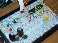
OverviewThe Phone Call Monitoring Facility's full schematic diagram is available in PDF format, by clicking the tile below.
The hardware of the device contains four distinct parts:
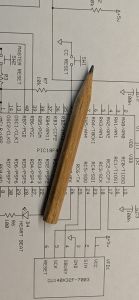
Power SupplyThe device is powered from a "wall wart" adapter, which provides full-wave-rectified and filtered 9 V DC; this is then stepped down to 5 V DC by a 7805 linear regulator. Since the filaments of the vacuum fluorescent display need to be heated (see below [↓]), the VFD alone can pull up to 520 mA of current; because of this, the regulator requires a sizeable heat sink. Ring Signal DetectorThe ring signal is a pure sinusoidal AC waveform, with a root mean square (RMS) amplitude of 40 to 100 V and a frequency of 16 to 67 Hz (typically 20 Hz in the US), which is superimposed on the phone line to make the telephone set ring. Our ring signal detector follows the classic design, which uses a capacitor to block the DC component, and a pair of Zener diodes connected in series cathode-to-cathode to clamp the peak-to-peak voltage of the signal. In the PCMF's case, the Zener voltage was chosen to be 15 V, which is low enough to ensure that even weak ring signals can produce a wide plateau. This clamped signal drives the transmit-side of an optocoupler, whose receive-side is connected to one of the MCU's GPIO's. (The use of optocouplers is common in telephony circuits, as it provides electric isolation from the phone line that is dangerously exposed to the elements.) In order to limit the current through the optocoupler, the circuit also includes a series resistor; our design uses a trimmer potentiometer that was adjusted to ensure that the ring signal is picked up reliably, but the audio waves are ignored. One more thing to keep in mind was that the negative half-cycles of the ring signal would reverse-bias the optocoupler's LED to voltage levels beyond its tolerance. The typical remedy to this is adding a diode in parallel to it with opposite polarity, so that the two diodes can watch each other's back. In our circuit, we took this idea one step further and used an LED instead, which begins flashing when the ring signal is present - this proved to be an excellent diagnostic aid during debugging. The original circuit also appears in James Darwood's ring detector patent, which also includes a mechanism to distinguish the ring signal from the dialing pulses of an old rotary phone - on the PCMF, this is done purely from firmware (see the PCMF Firmware page). MicrocontrollerMonica and I spent a decent amount of time with the parts selection, and settled with the PIC18F4520 device. Like the PIC16xxx series, this is also a Harvard architecture, but with 16384 words of flash program memory and 1536 bytes of static RAM. It also has an extended instruction set and additional index registers, making the MCU more suitable for firmware development in high-level languages, for example C. There is also a wide range of built-in peripherals, which was a bit of an overkill for this project, but we also kept possible future expansions in mind. Even though the heart of the ring signal analysis is the measurement of time periods, the accuracy of these measurements is not tremendously critical - therefore we opted for clocking the device from its 8 MHz internal oscillator, which required no additional external components. Vacuum Fluorescent DisplayVacuum fluorescent displays (VFD's) are a type of display technology that uses phosphor-coated anodes to emit light when struck by electrons expelled from a grid of heated filaments serving as the cathode. Like the Nixie tube, this technology has also been replaced by the cheaper, less fragile and more energy-efficient LED and LCD alternatives, but is still popular among hobbyists for its classy, vintage appeal.
The PCMF uses a Noritake Itron GU140X32F-7003 VFD module, which was a generous donation by the manufacturer to our university. It is a 140×32-pixel graphics display, but can also be operated in character mode, when it fits 20×4 single-size or 10×2 double-size characters on the screen. The module manages all the power requirements for the VFD element, and also includes a built-in controller that accepts ASCII character codes and control command codes through its serial interface and drives the pixels accordingly. The device can communicate over the UART and SPI protocols, which are also supported by the PIC's built-in peripherals. With both choices available, we opted for SPI, as it is easier to debug by visually inspecting the signals on an oscilloscope or logic analyzer, should it become necessary. |
||||||

|